PPS Analyzer


NetTimeLogic developed a PPS analyzer specifically for (PTP) Plugfests where multiple devices are synchronizing each other, and the accuracy of the individual devices shall be measured via PPS (offset from reference PPS). The device has 8 PPS inputs that are measured simultaneously, and it synchronizes itself to an additional reference PPS input. Additionally, it has a PPS output of the synchronized clock which is used for PPS measurement. Multiple PPS Analyzers can be connected to the same host and are all discovered automatically. It uses a serial interface (mostly over USB) or Ethernet to access the registers in the FPGA. In the FPGA it uses NetTimeLogic's configuration IP (free of charge) which represents an AXI Master to the other IP cores. It uses a proprietary protocol to convert the serial data stream from/to AXI register access. The core part consists of the following NetTimeLogic IP cores: PPS Slave IP core, PPS Master IP core, Adjustable Counter Clock IP core and multiple instances of the Signal Timestamper IP core. The tool needs no configuration and self-discovers all cores available in the design. It allows to access all registers in the design (also third party) which are connected to the AXI bus.
It allows to save the measurement screen as JPG, PNG or TIFF and can log the measured values as CSV.
The application is written with Qt as GUI framework and is currently available for Windows. The measured offsets are read by the PPS Analyzer application via UART and shown in a chart.
Block Diagram

Hardware
The hardware used for the PPS Analyzer consists of a custom PPS shield for the ArtyA7-35T (no longer in production), ArtyA7-100T or ArtyS7-50 boards from Digilent.
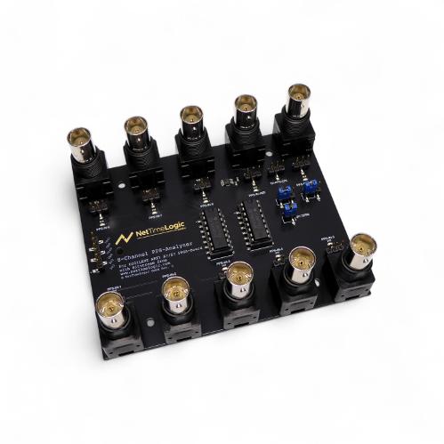
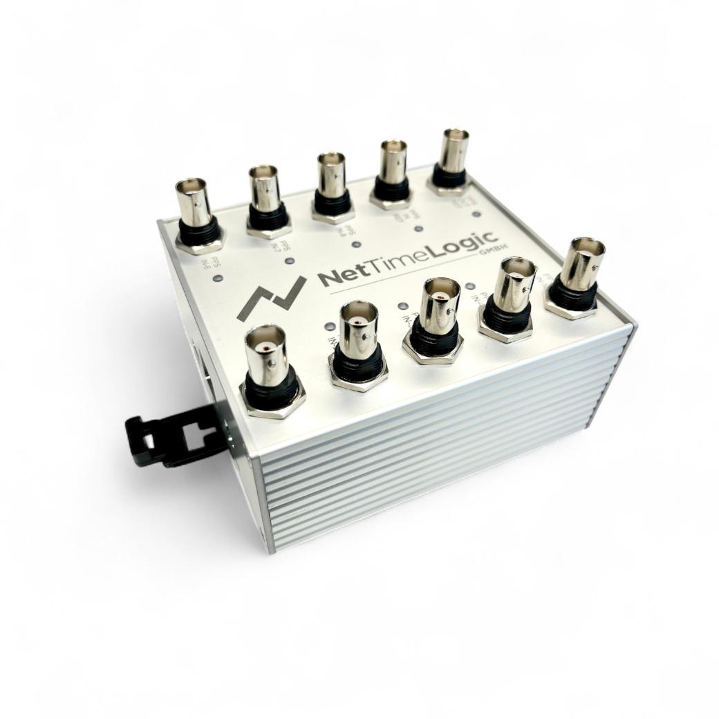
PPS Analyzer shield from NetTimeLogic without and with aluminum case
Universal PPS Analyzer Tool
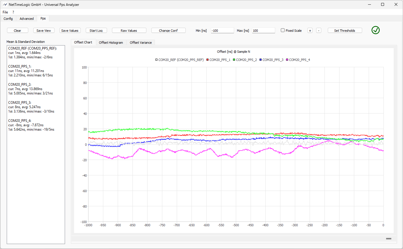
Grey: Reference PPS, Colored: PPS from devices under test
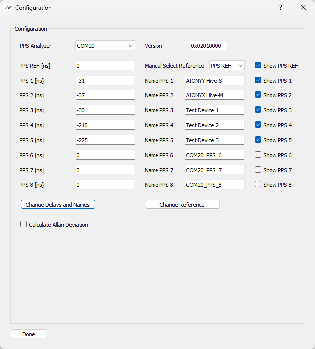
This is the screen to change the individual delays in case cable delays differ or if some additional buffers are in place
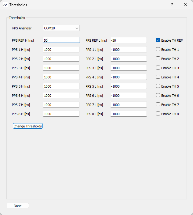
This is the screen to set threshold values which will be signaled on additional pins if exceeded and indicated in the GUI
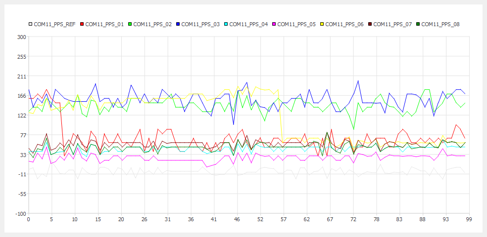
This is a saved screen (you can save the current screens as PNG, TIFF or BMP) from the swiss PTP Plugfest 2017
Features
- 8 PPS inputs per analyzer
- 1 reference PPS input per analyzer
- 1 PPS output per analyzer
- Synchronized Clock via PPS
- Timestamp resolution 1ns with TDC
- USB-UART or Ethernet connection (Ethernet only available with ArtyA7-35T or ArtyA7-100T)
- Multi Analyzer and Multi User capable
- PPS compensated for synchronization error introduced by the reference PPS
- Multiple Analyzers supported (in the same Screen)
- Individual Delay compensation per PPS
- Enable and disable individual PPS
- Renaming of PPS signals
- Optional EEPROM for Buffer delay compensations and storage of IP and MAC
- Optional Threshold configuration and signals to alarm when the offset exceeds the defined range
- Auto scale or fixed scale
- Long-term measurements (up to 100000 seconds with sliding screen window)
- Self-discovery of all Analyzers
- Save screen as PNG, TIFF or BMP
- Log values as CSV
- Min, Max, Mean and Standard Deviation shown
- Python Script for measurements from a script or custom measurements
Pricing
All prices are in US Dollars without VAT and shipping costs. The prices are without the ArtyA7-35T/ArtyA7-100T/ArtyS7-50 board from Digilent, this has to be purchased individually:
- Assembled and calibrated PPS Analyzer SMD Shield:
- Ready to run PPS Analyzer Shield, assembled and calibrated
- Pre-assembled and calibrated PPS Analyzer SMD Shield with aluminum case
- Ready to run PPS Analyzer Shield, pre-assembled and calibrated
- Aluminum case which can be mounted on a DIN rail

All prices are non-binding estimates – please use the contact form for definitive pricing and lead-time information or check the stock in our Shop.
Downloads

|
Upa_UniversalPpsAnalyzer_Flyer.pdf Size : 212.069 Kb Type : pdf |

|
Upa_UniversalPpsAnalyzer_ReferenceManual.pdf Size : 1201.7 Kb Type : pdf |
GitHub
The whole project can be found as sources on NetTimeLogic's Github account:
https://github.com/NetTimeLogic-OpenSource/UniversalPpsAnalyzer
Get involved
Contact us if you would like to contribute to the development of this open source project
